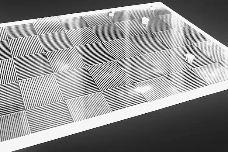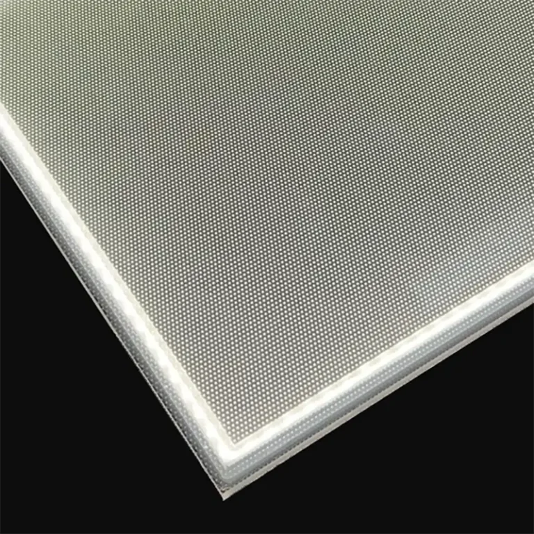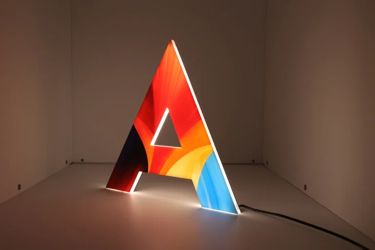
A laser-dotted light guide plate is manufactured by creating a controlled pattern of optical dots on a transparent PMMA acrylic plate.
However, laser processing is only one stage of the complete manufacturing process.
For a custom project, the final light effect also depends on:
- Product dimensions
- PMMA thickness
- LED type and position
- Light-entry sides
- Single-sided or double-sided output
- Reflector and diffuser configuration
- Holes, cut-outs, and irregular shapes
- Target brightness and uniformity
- Final mechanical assembly
For this reason, custom light guide plate manufacturing normally begins with project evaluation and structural planning—not with immediate laser processing.
The general workflow is:
Project requirements → engineering evaluation → structural proposal → PMMA machining → optical dot-pattern design → laser dotting → assembly → prototype testing → customer approval → mass production → full inspection → protective packaging
Quick Answer
Laser-dotted light guide plates are manufactured by first confirming the required dimensions, optical effect, LED arrangement, and product structure.
The PMMA sheet is cut and machined to the required shape, including holes, cut-outs, chamfers, and polished light-entry edges where necessary. Engineers then generate a customized optical dot pattern based on the product dimensions and required brightness.
The pattern is transferred to the PMMA surface using laser processing equipment. The plate may then be assembled with LEDs, reflective material, and a diffuser for prototype testing.
Brightness, uniformity, dark areas, bright edges, and overall visual performance are inspected. If necessary, the optical pattern or structure is adjusted and tested again.
After the customer approves the sample, the confirmed dot-pattern file and production settings are used for mass production.
Manufacturing Is More Than Laser Dotting
It is easy to describe a laser-dotted light guide plate as an acrylic sheet processed by a laser machine.
That description is incomplete.
The laser machine produces the optical microstructures, but it does not independently determine whether the finished product will have:
- Sufficient brightness
- Acceptable uniformity
- Controlled bright edges
- No obvious dark areas
- Suitable diffusion
- Correct LED coupling
- Stable mass-production performance
Research on light guide plates has shown that the dimensions, density, distribution, and arrangement of optical microstructures directly affect light extraction and luminance uniformity.
The manufacturing process must therefore combine mechanical fabrication, optical pattern design, LED configuration, prototype testing, and quality control.
Step 1: Collect and Clarify the Project Requirements
The process begins with understanding what the customer is trying to produce.
Different customers provide different levels of information.
Customers with complete technical information
Some customers provide:
- Product dimensions
- 2D or 3D drawings
- LED specifications
- LED positions
- Product structure
- Target brightness
- Uniformity requirements
- Diffuser and reflector information
- Installation conditions
- Expected production quantity
These projects can normally move directly into technical evaluation.
Customers with an initial project proposal
Other customers may know the intended application but have not finalized the complete structure.
For example, they may know that the light guide plate will be used in:
- A retail display
- An advertising light box
- A display cabinet
- An appliance
- A piece of equipment
- An illuminated sign
- A decorative backlit panel
In these cases, the manufacturer may need to recommend a plate thickness, light-entry arrangement, LED position, optical layers, or preliminary structure.
Customers with only a concept
Some customers begin with a concept rather than a finished drawing.
For concept-stage projects, the manufacturer first evaluates:
- Project scale
- Technical feasibility
- Expected development work
- Required engineering support
- Prototype requirements
- Potential production volume
The level of development support is then determined according to the project scope and feasibility.
A clear commercial and technical evaluation is important because the dimensions alone are rarely sufficient to design a custom light guide plate.
Step 2: Business and Engineering Evaluation
After receiving the available project information, the business and engineering teams evaluate the requirements together.
The business team clarifies the application, purchasing requirements, expected quantity, schedule, and communication with the customer.
The engineering team evaluates the optical and structural feasibility.
Typical points include:
- Is a light guide plate suitable for the application?
- What PMMA thickness may be required?
- Which edge or edges can accommodate LEDs?
- Is single-edge, double-edge, or multi-edge lighting needed?
- Is the product single-sided or double-sided?
- Are there holes, openings, or irregular edges?
- What brightness and uniformity are expected?
- Is there enough space for a diffuser and reflector?
- Will the customer purchase only the plate or a complete assembly?
- Is prototype verification required?
This stage is also used to identify missing information.
When the customer has only provided dimensions, the engineering team does not immediately create a production file. The structure, LEDs, light-entry method, optical materials, and expected visual effect must first be clarified.
Step 3: Develop the Structural and Optical Proposal
Based on the evaluation, a preliminary product solution is prepared.
The proposal may define:
- PMMA material
- Plate thickness
- External dimensions
- Hole and cut-out positions
- Light-entry edges
- LED positions
- Number of LED sides
- Single-sided or double-sided output
- Reflector arrangement
- Diffuser arrangement
- Mechanical installation method
- Required component spacing
A solution drawing may then be submitted to the customer for review.
This drawing allows both parties to confirm the intended structure before physical production begins.
Why structural confirmation matters
The optical dot pattern is connected to the complete product structure.
For example, changing from single-edge to double-edge lighting may require a different pattern. Moving an LED strip, changing the PMMA thickness, or reducing the distance to the diffuser may also affect the finished appearance.
The product structure should therefore be reasonably stable before the sample pattern is finalized.
Step 4: Prepare and Machine the PMMA Plate
PMMA acrylic is widely used as a light guide plate material because of its optical characteristics and suitability for forming light-extraction structures.
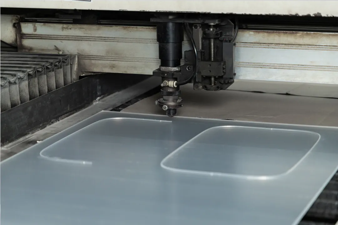
In our process, the PMMA plate is normally cut and mechanically processed before laser dotting.
Depending on the customer’s drawing, the machining stage may include:
- Cutting to length and width
- Custom-shaped cutting
- Creating holes
- Creating internal cut-outs
- Chamfering
- Edge polishing
- Processing the required light-entry edges
Why machining is completed first
The optical pattern is designed around the final product shape.
If the product contains openings, irregular edges, or unusual LED positions, these features influence how light travels through the plate.
Completing the main external machining first provides a defined geometry for the subsequent optical pattern and laser-dotting process.
It also reduces the risk that later cutting will remove or disturb important areas of a customized dot pattern.
Step 5: Design the Optical Dot Pattern
After the product dimensions and structure are established, the optical dot pattern is prepared.
The pattern is not simply a uniform arrangement of identical dots.
The design considers information such as:
- Plate dimensions
- Plate thickness
- LED position
- Number of illuminated edges
- Distance from each area to the LED source
- Target brightness
- Target uniformity
- Holes and cut-outs
- Irregular shapes
- Single-sided or double-sided output
- Reflector and diffuser structure
Software is used to generate the initial optical pattern.
The dot size, density, spacing, and distribution may vary across the panel to control how much light is extracted from different areas.
Academic studies and industrial research have demonstrated that modifying dot distribution is an important method of improving light extraction and luminance uniformity.
Why each pattern may be different
A dot pattern developed for one product cannot always be reused for another.
The pattern may need to change when the customer changes:
- Overall dimensions
- Plate thickness
- LED pitch
- LED power
- Light-entry sides
- Shape
- Hole positions
- Diffuser
- Required brightness
- Required viewing effect
For this reason, a laser-dotted light guide plate is not merely a cut-to-size acrylic sheet. It is a customized optical component designed around the intended product.
Information that remains proprietary
A customer-facing manufacturing article does not need to disclose:
- Dot-generation algorithms
- Exact dot dimensions
- Dot-density formulas
- Laser power
- Laser speed
- Processing frequency
- Machine settings
- Pattern-correction methods
- Internal optical databases
- Numerical acceptance thresholds
These are part of the manufacturer’s internal process and engineering experience.
Step 6: Laser-Dot the Light Guide Plate
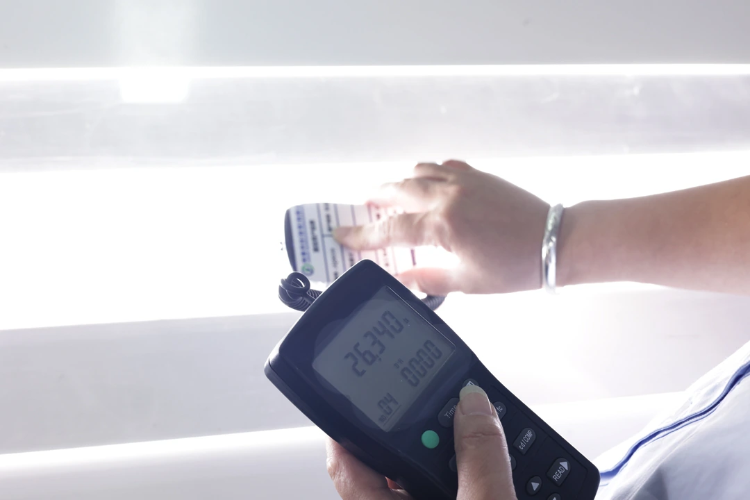
After the optical file is prepared, the pattern is transferred to the PMMA plate using laser processing equipment.
The laser creates controlled scattering structures on the plate surface.
When light from the LEDs travels through the PMMA and reaches these structures, part of the light is redirected out of the plate, forming surface illumination.
Laser processing has been studied as a method for creating light-extraction patterns on PMMA light guide plates, and the resulting microstructure characteristics are influenced by the processing conditions.
During production, the plate must be positioned and processed according to the confirmed file and internal manufacturing settings.
The specific laser parameters are controlled internally and are not part of the customer-facing technical documentation.
Step 7: Install LEDs and Optical Materials
After laser dotting, the plate can be assembled for optical testing.
Depending on the customer’s required delivery scope, the assembly may include:
- LED strips
- Reflective film
- Diffuser
- Wiring
- Power components
- Frame or housing
- Other supporting optical or mechanical parts
Function of the LED source
The LEDs introduce light through one or more edges of the PMMA plate.
Their output, spacing, position, beam characteristics, and alignment influence how much light enters the plate.
Function of the reflector
The reflector is normally positioned behind the light guide plate.
It redirects backward-travelling light toward the intended output surface and helps improve usable light output.
Function of the diffuser
The diffuser blends the extracted light and reduces the visibility of individual laser dots, bright areas, or local differences.
A suitable diffuser and correct spacing are important to the finished appearance.
The customer may also request only the processed light guide plate. In that case, LEDs and optical materials can be installed by the customer according to the confirmed structure.
Step 8: Conduct Prototype Lighting Tests
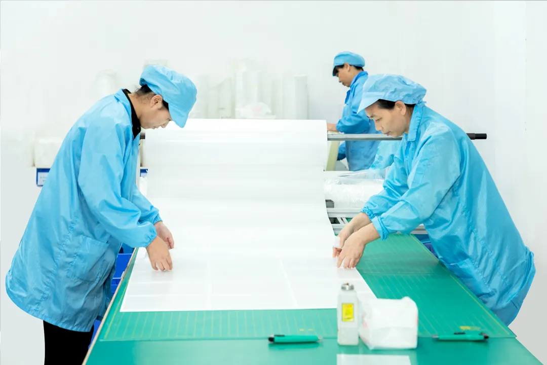
The first processed plate is assembled and illuminated for evaluation.
The prototype is checked for:
- Overall brightness
- Surface uniformity
- Dark areas
- Bright edges
- LED hotspots
- Visible dot patterns
- Corner performance
- Light distribution around holes and cut-outs
- Overall visual effect
Each of these observations provides information about whether the optical pattern and product structure are working together correctly.
Why the first sample may require adjustment
Software generates the initial dot pattern, but the final product contains physical variables that may affect the result.
These include:
- Actual LED output
- PMMA variation
- Edge coupling
- Component tolerances
- Diffuser transmission
- Reflector performance
- Assembly spacing
- Mechanical positioning
Prototype testing is therefore used to verify the real illuminated result.
If the light effect does not meet the required target, the engineering team may adjust the pattern or relevant product structure and produce another sample.
The detailed adjustment method remains part of the internal engineering process.
Step 9: Submit the Sample for Customer Approval
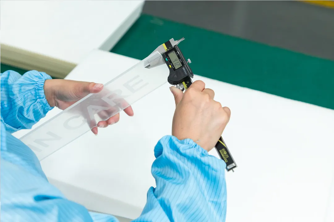
After internal testing, the sample is submitted to the customer for evaluation.
Depending on the project, the customer may review:
- Dimensions
- Shape
- Hole positions
- Assembly fit
- Brightness
- Uniformity
- Color temperature
- Surface appearance
- Diffusion
- Viewing effect
- Electrical configuration
- Installation method
The customer may also test the sample inside the final product or installation environment.
This is particularly important when the light guide plate must work with components supplied by the customer.
What is confirmed at the sample stage
Once the sample is approved, the confirmed production basis may include:
- Product drawing
- PMMA specification
- Plate thickness
- Dot-pattern file
- LED arrangement
- Reflector and diffuser structure
- Assembly method
- Visual reference
- Other agreed production requirements
These confirmed elements form the reference for mass production.
Step 10: Lock the Production Standard
After sample approval, the corresponding dot-pattern file and production settings are retained for mass production.
The purpose of locking the standard is to avoid uncontrolled changes between the approved sample and the production order.
Mass production should use the confirmed:
- Product dimensions
- Machining drawing
- Optical pattern
- LED arrangement
- Optical components
- Assembly requirements
- Production settings
- Inspection criteria
If the customer later changes the dimensions, LEDs, structure, diffuser, or expected light effect, the impact must be evaluated.
A major change may require a revised pattern and another sample confirmation.
Step 11: Begin Mass Production
The mass-production process follows the approved sample and confirmed manufacturing information.
The main stages generally include:
- PMMA material preparation
- Cutting and external machining
- Hole and custom-shape processing
- Edge treatment or polishing
- Laser dotting
- LED and optical-material installation, if required
- Product assembly
- Lighting inspection
- Surface inspection
- Protective-film application
- Packaging
The exact process may vary according to whether the order is for:
- A processed light guide plate
- A light guide plate assembly
- A complete illuminated product
Step 12: Inspect Every Finished Unit
Finished products are fully inspected before packaging.
The inspection includes both physical appearance and lighting performance.
Surface inspection
The surface is checked for issues such as:
- Scratches
- Damage
- Contamination
- Incorrect dimensions
- Incorrect holes or cut-outs
- Edge defects
- Other visible processing problems
PMMA surfaces require appropriate protection because scratches and contamination may become more visible after illumination.
Lighting inspection
For illuminated units or assembled samples, the inspection includes:
- Brightness
- Uniformity
- Dark areas
- Bright edges
- Overall light effect
- Visible LED hotspots
- Visible dot patterns under the intended structure
- General consistency with the approved sample
The article intentionally does not disclose internal numerical acceptance thresholds.
The purpose of inspection is to confirm that each finished unit matches the agreed structure and visual standard before shipment.
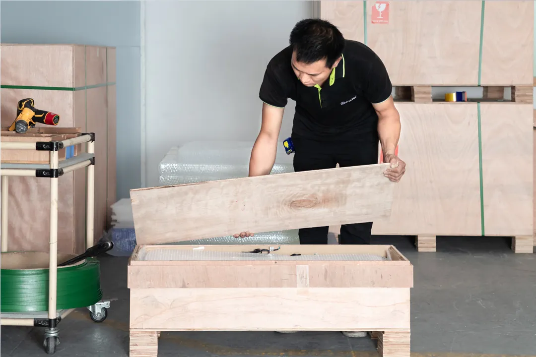
Step 13: Apply Protective Film and Package the Product
After inspection, protective film is applied to the light guide plate surface.
The film helps reduce the risk of:
- Surface scratches
- Dust
- Contamination
- Handling damage
The protective film should normally remain in place until installation or final assembly.
Wooden-crate packaging
Light guide plates, particularly larger panels, can be packaged in wooden crates for transportation.
The packaging method is selected according to:
- Plate dimensions
- Plate thickness
- Quantity
- Delivery form
- Transportation method
- Destination
- Risk of bending or impact
Large-format PMMA panels require appropriate structural support during shipping because their size increases handling and transportation risk.
Available Delivery Formats
A laser-dotted light guide plate project can be delivered at different levels of completion.
| Delivery format | Included items |
| Processed light guide plate | Cut and laser-dotted PMMA plate |
| Light guide plate component | Light guide plate with selected LEDs, reflector, diffuser, or supporting components |
| Complete illuminated product | Finished lighting assembly produced according to the confirmed structure |
The correct delivery format depends on the customer’s manufacturing capability, supply chain, product design, and assembly requirements.
Customers with their own LED and assembly resources may order only the light guide plate.
Customers seeking a more integrated solution may request optical components or a complete illuminated product.
Why Is Prototype Testing Important?
Prototype testing connects the theoretical design with the real product.
A design file cannot fully represent every manufacturing and assembly variable.
The sample confirms whether:
- The selected PMMA thickness is suitable.
- The LED arrangement provides sufficient input light.
- The dot pattern distributes light correctly.
- The diffuser provides the expected appearance.
- The reflector improves usable output.
- The holes and cut-outs affect the light as expected.
- The complete structure fits the intended application.
- The visual result meets the customer’s expectations.
Skipping prototype verification may increase the risk of discovering optical or structural problems after mass production has begun.
For custom, large-format, irregular, thin, double-sided, or visually demanding products, sample confirmation is particularly important.
What Information Should Customers Provide?
The following information helps shorten the evaluation and development process:
| Required information | Why it matters |
| Application or project description | Defines the intended use and viewing conditions |
| Product dimensions | Determines the plate size and light-travel distance |
| Technical drawing | Confirms shape, holes, cut-outs, and tolerances |
| LED specification | Affects light input and optical-pattern design |
| LED position | Determines the light-entry arrangement |
| Required brightness | Helps define the optical and electrical structure |
| Uniformity expectation | Determines the required level of pattern optimization |
| Single- or double-sided output | Changes the optical structure |
| Diffuser and reflector details | Affect the final light distribution |
| Installation space | Determines available product depth |
| Normal viewing distance | Affects acceptable dot visibility and diffusion |
| Expected quantity | Influences prototype and production planning |
| Required delivery format | Defines whether the order includes only the plate or a complete product |
Customers without complete technical information can initially provide the application, approximate dimensions, expected visual effect, and available installation space.
The business and engineering teams can then identify the additional information required for evaluation.
Common Misunderstandings About Laser-Dotted Light Guide Plate Manufacturing
The same dot pattern can be used for every size
This is generally incorrect.
Changing the plate dimensions changes the distance between different areas of the plate and the LED source. The pattern may need to be redesigned or adjusted.
Laser dotting is the first manufacturing step
In our process, the plate is normally cut, shaped, drilled, chamfered, and polished as required before the customized dot pattern is processed.
A customer only needs to provide the length and width
Dimensions are important but insufficient for a complete optical design.
LED positions, light-entry sides, brightness, uniformity, diffuser, reflector, output direction, and application structure also need to be evaluated.
Software eliminates the need for testing
Software helps generate the initial optical pattern, but prototype lighting tests are still needed to evaluate the actual materials, LEDs, optical layers, and assembly.
Every laser-dotted plate is delivered as a complete light panel
Customers can order only the processed light guide plate, a light guide plate component, or a complete illuminated product.
Laser processing alone guarantees uniform lighting
Uniformity depends on the complete system, including the dot pattern, LEDs, PMMA, edge coupling, reflector, diffuser, dimensions, and assembly.
Frequently Asked Questions
Do laser-dotted light guide plates require a mold?
No. The optical dots are created through laser processing, so a mold is not required for the laser-dotting stage.
This makes the process suitable for prototypes, custom projects, and small-volume production.
Is the PMMA cut before or after laser dotting?
In our manufacturing process, the PMMA plate is normally cut and externally machined before laser dotting.
The final shape, holes, cut-outs, and light-entry edges can affect the optical design.
How is the dot pattern designed?
Software is used to generate an initial dot pattern according to the product dimensions and required optical effect.
The pattern is then verified through prototype testing and adjusted when necessary.
The detailed algorithm and processing parameters remain proprietary.
Can laser-dotted light guide plates include holes and custom shapes?
Yes.
Custom shapes, holes, cut-outs, chamfers, and polished edges can be produced according to the project drawing.
These features must be considered during optical evaluation.
Is every project tested before mass production?
For a custom project, a prototype is normally produced and tested before mass production.
The sample is submitted to the customer for approval, after which the confirmed pattern and production settings are used for the batch order.
What is checked during lighting inspection?
The main inspection items include brightness, uniformity, dark areas, bright edges, and overall light effect.
The plate surface is also inspected for scratches and other visible defects.
Can you install LEDs, reflectors, and diffusers?
Yes.
The delivery can include only the processed light guide plate, a light guide plate component with selected optical materials, or a complete illuminated product.
What happens if the prototype is not uniform?
The test result is evaluated by the engineering team.
The optical pattern or relevant structure may be adjusted, followed by another prototype and lighting test.
The specific correction method is part of the internal engineering process.
Are all finished products inspected?
Yes.
Each finished unit is inspected for surface condition and, where applicable, lighting performance before protective film and packaging are applied.
How are large light guide plates packaged?
Protective film is applied to the PMMA surface, and wooden-crate packaging can be used to protect the panels during transportation.
The specific packaging structure depends on the size, thickness, quantity, and shipping method.
Conclusion
Manufacturing a laser-dotted light guide plate is not a single laser-processing operation.
It is a coordinated process involving:
- Project requirement clarification
- Business and engineering evaluation
- Structural planning
- PMMA cutting and machining
- Optical dot-pattern design
- Laser processing
- LED and optical-material assembly
- Prototype lighting tests
- Customer sample approval
- Production-standard locking
- Mass production
- Full inspection
- Protective packaging
The dot pattern is central to light distribution, but the finished result also depends on the LEDs, PMMA thickness, light-entry structure, reflector, diffuser, dimensions, and mechanical assembly.
A reliable custom project should therefore begin with a complete evaluation of the intended application rather than with the plate dimensions alone.
Planning a custom laser-dotted light guide plate project?
Send your application information, dimensions, drawing, LED arrangement, required light effect, expected quantity, and preferred delivery format. Our business and engineering teams will review the requirements and prepare a preliminary solution for further discussion.